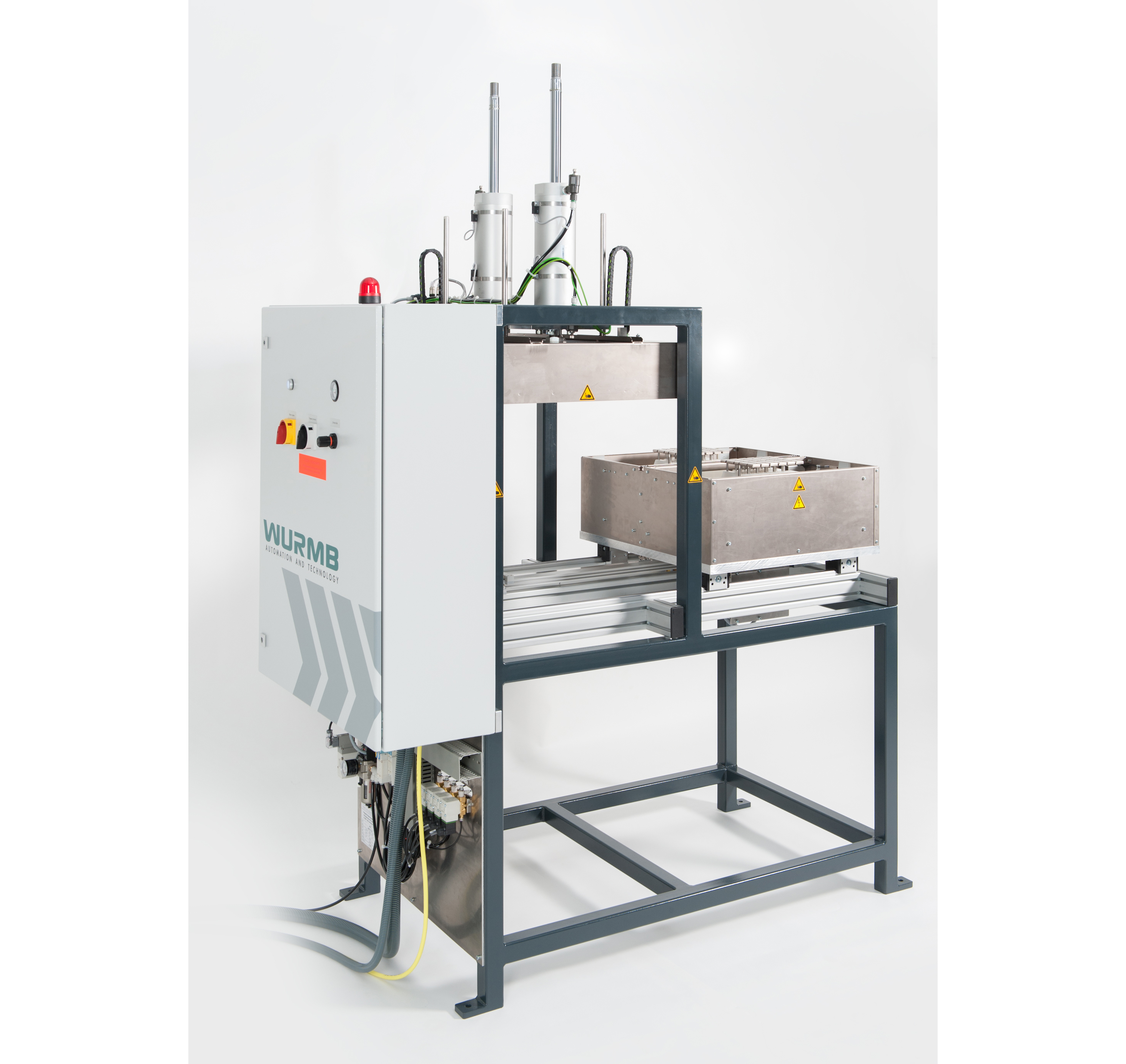
Testing Facility for Battery Boxes HSVD
Item 39092
Test system for integration into the production process directly after the injection molding machine
• Product handling by external robots
• Simultaneous testing of 2 test specimen
• Leak test based on a pressure loss test with p <100mbar
• High voltage test for the detection of material defects e.g. at the gates
• Test voltages up to 30,000V DC
• Easy replaceable test adapters
• Optional: touch control panel for parameterization and error display

Specifications
| Standard version |
|
| Structure of the system | The system consists of a welded shaped tube frame which contains the switch box, the pneumatic mounting plate and the movable test trolley including 2 holders for test adapters and the pressure cylinders. Additionally:
|
| Function | Simultaneous, parallel and independent testing of 2 battery boxes:
|
| Inserting the test specimens | Performed with an external robot. Test specimens are placed on the test adapter from above.
The test trolley with the installed test adapter moves into the test position. The locking cylinders press the battery boxes onto the test adapter with reduced pressure.
The correctly pressed-in battery boxes are checked by passing the lower limit switch of the locking cylinder. When the lower limit switch is passed, the system switches to the contact pressure. After the test, the clamping cylinders open, the test carriage moves back into the insertion position and the test specimens can be removed by the robot. The results are transferred to the injection molding machine. The contact pressure can be manually adjusted to the battery box size using a pressure reducing valve. |
| Technical data |
|
| Signals | Communication with spraying machine:
|
| Switch box | Mounted on the back (narrow side) of the appliance. Operating elements on the door: Main switch, high voltage off (service switch), pressure regulator with pressure gauge for setting the contact pressure |
| Control panel connection | The control panel can be plugged into the control unit at any time and is hot pluggable. |
| Connection box | Connection socket for control panel and "Fault" signal lamp, "Acknowledge fault" button. Connection to the control box of the test device: permanently connected, 7 m connection cable in plastic protective conduit. |
| Dimensions | W= 1,640mm, D=800mm, Hmax=2,341mm Frame height: 1,700mm, when pressure cylinder is retracted: 2,091mm |